
Linear Actuator Backdriving and Self-Locking: An OEM Procurement Guide to Holding Loads, Power-Off Brakes, and Anti-Drift Safety
Compare linear actuator backdriving, self-locking screws and power-off brakes. Use an OEM holding-load checklist to review supplier evidence and prepare an RFQ.
Last Updated: October 26, 2026
Executive conclusion: Linear actuator backdriving occurs when an external load drives the screw and motor backward. Low-lead sliding screws may self-lock under specified conditions; high-lead screws and rolling-element drives require a verified holding strategy when the load can drive the axis. Select the holding device, brake location and power-loss response from the load path and machine risk assessment, then request supplier evidence for the complete assembly. A brake or a “self-locking” label alone does not establish machine safety.
1. The Operational Danger of Uncontrolled Backdriving
When specifying custom linear actuators for industrial automation, medical robotics, material handling, or mobile heavy equipment, the primary performance criteria usually focus on push/pull force, speed, stroke, and supply voltage. However, what happens when power is removed or cut unexpectedly?
Backdriving—also referred to as reverse-driving or mechanical overhaul—occurs when an external axial force applied to the actuator rod forces the internal drive screw, gearbox, and motor shaft to rotate backward in the absence of motor driving torque.
In horizontal push-pull tasks (such as automated conveyor gates or inspection slide tables), backdriving may only cause minor positioning loss. However, in vertical or gravity-overhauling configurations (such as patient lift tables, scissor lifts, engine hoods, ag-drone battery swapping bays, or overhead damper doors), backdriving can cause an uncontrolled descent of the suspended mass.
For machine builders, distributors, and procurement managers, backdriving failure can cause:
- Severe Personnel Safety Hazards: Falling mechanisms crush hands or limbs, triggering liability under machinery directives.
- Micro-Creep Under Machine Vibration: An actuator that holds steady in a static factory floor test slowly loses position over hours of machine vibration, drifting out of alignment.
- Regeneration & Driver Damage: A backdriving permanent magnet motor can generate voltage; a driver without a suitable energy path may experience DC-bus overvoltage.
- Mechanical Wear: Repeated unintended motion or impact can accelerate wear; the failure mode depends on the screw, nut, bearings and load path.
Scope and limits: This Global-English guide covers OEM screening of DC brushed, BLDC and AC-driven rod-style electromechanical actuators. EU requirements below apply to machinery within their scope; other markets and medical or personnel-lifting applications need their own applicable rules. Calculations are illustrative engineering estimates, not measured product data or safety certification. Release decisions require assembly-specific ratings and a machine risk assessment. Editorial review date: October 26, 2026.
Start Here: Pair this evaluation with our OEM Linear Actuator RFQ Checklist, Ball Screw vs. Planetary Roller Screw Sourcing Guide, and review our continuous-duty linear actuator architecture before submitting custom specifications to our engineering team.
2. The Physics of Self-Locking: Lead Angle vs. Friction Angle
To eliminate backdriving risks at the RFQ stage, procurement teams must understand the physical mechanism governing screw efficiency. An electromechanical actuator converts rotational torque into linear thrust through a threaded helical shaft—either a sliding-contact power screw (Acme / Trapezoidal) or a rolling-element screw (Ball / Planetary Roller).
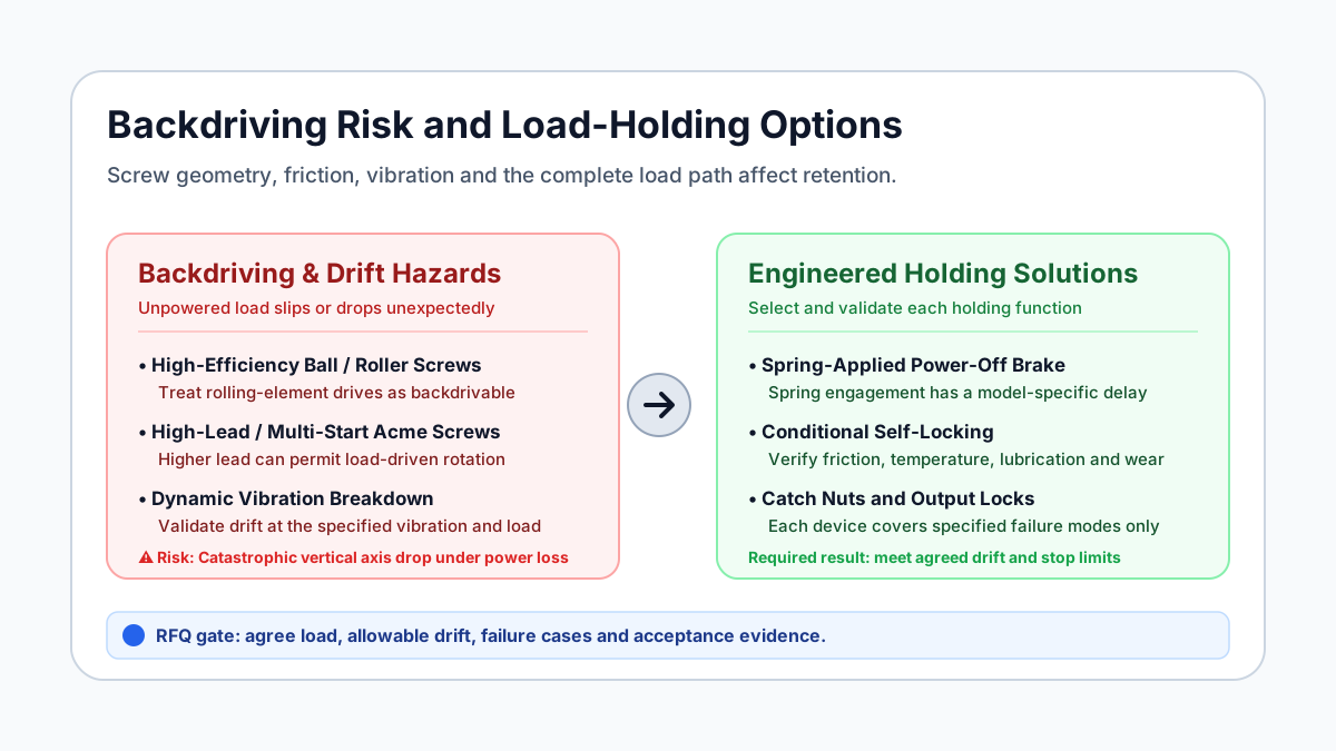
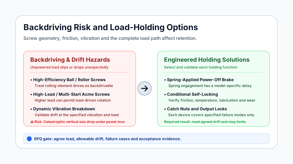
Figure 1: Conceptual holding options and their validation limits; this diagram is not a certified safety architecture.
The Mathematical Threshold of Self-Locking
Use consistent length units for screw lead L and mean pitch diameter d_m:
Lead angle:     lambda = arctan(L / (pi * d_m))
Friction angle: phi = arctan(mu_effective)
Lowering torque at the screw: T_lower = F * d_m / 2 * tan(phi - lambda)
Here F is the axial load and mu_effective is the effective thread friction coefficient. This is a simplified square-thread model, excluding collar and bearing drag. For Acme/trapezoidal threads, a common approximation is mu_effective = mu / cos(alpha), where alpha is the thread half-angle; use the supplier's model for the actual profile. The model is not a ball/roller-screw contact calculation.
- Self-locking in the model (
lambda < phi): Positive lowering torque is needed to initiate motion. This is conditional on the assumed friction, geometry and loading; it does not prove retention under vibration or wear. - Near the boundary (
lambda ≈ phi): Small friction changes can change the direction of the torque needed to lower the load. - Backdrivable (
lambda > phi): The load can drive rotation. A brake at the screw must oppose the magnitude of the resulting torque; a motor-mounted brake requires conversion through the gearbox and a separately justified design margin.
Do not substitute nominal outside diameter for pitch diameter or confuse lead with thread pitch on a multi-start screw.
3. The "Self-Locking Acme" Myth: Why Modern Lead Screws Backdrive
A widespread rule of thumb among sourcing personnel is: "Acme and trapezoidal lead screws are self-locking; ball screws are backdrivable."
While true for standard single-start, low-lead miniature jacks, this rule of thumb is frequently false in modern industrial OEM actuators.
The Problem with High-Lead and Multi-Start Screws
Designers can increase linear speed without increasing motor speed by increasing screw lead, including with multi-start threads. The higher lead angle can remove a screw's self-locking tendency.
Illustrative calculation, not a product test: Assume a four-start screw with a 12 mm mean pitch diameter, 12 mm lead and effective friction coefficient mu_effective = 0.12. Its lead angle is arctan(12 / (pi * 12)) = 17.66°; its friction angle is arctan(0.12) = 6.84°. The simplified model predicts backdriving. These assumed friction and dimensions must be replaced with supplier data before selection.
Mechanical Efficiency as a Screening Clue
Thomson's lead-screw brochure, printed page 5, identifies low lead as a factor in self-locking and gives approximately 50% efficiency as a backdriving rule of thumb. It is a screening clue, not an assembly holding-load guarantee. Ask for evidence at the specified load, lubrication, temperature and wear condition; do not approve a vertical axis from efficiency alone.
4. The Vibration Trap: Static Friction vs. Dynamic Slip
A shallow-lead screw that holds on a stationary bench may still lose position under operating vibration. Verify the complete assembly under the specified conditions rather than extending the bench result to every installation.
The Physics of Friction Degradation
Vibration and shock can disturb contact and initiate slip. Running friction may differ from breakaway friction, and lubrication, temperature, wear and mounting stiffness can change the result. There is no universal vibration threshold below which every “self-locking” actuator is safe.
Possible symptoms include an access hatch creeping open, tooling losing clearance, or a positioning axis drifting. These are failure scenarios, not reported field measurements.
Procurement rule: Specify the vibration spectrum, shock pulses, load direction, temperature range and permitted drift over a defined dwell time. Require a guarded, assembly-level power-off retention test under those conditions. If movement creates a hazard, select additional holding measures through the machine risk assessment instead of relying solely on a stationary bench test.
5. Ball Screws & Roller Screws: Backdriving Must Be Evaluated
High-efficiency rolling-element screws are common in high-duty or high-force applications; see our ball screw vs roller screw sourcing guide. Treat the screw as potentially backdrivable unless the supplier establishes the complete assembly's power-off holding behavior.
An overhauling load may accelerate the axis, drive the motor as a generator and overload an end stop. Descent speed depends on inertia, gearing, friction and the electrical circuit; a screw type or a 3,000 N load alone cannot establish a free-fall speed.
For a hazardous gravity-loaded axis, document how the load is retained on loss of torque and how a moving load is stopped. Static holding and emergency stopping are separate capabilities.
6. Power-Off Holding Brake Architectures: Where and How to Lock
When an actuator cannot rely on thread friction, how does the system prevent backdriving? Modern custom linear actuators utilize three primary holding architectures. Understanding their mechanical locations and failure modes is vital for procurement validation.
Architecture A: Spring-Applied Electromagnetic Motor Brakes (Power-Off Brakes)
The most common industrial solution is an electromagnetic brake mounted directly onto the rear shaft of the electric motor.
- Operating Principle: This is a spring-applied, electrically released brake, often called a "power-off" brake. That name describes its actuation principle, not a system safety certification. Heavy-duty internal compression springs continuously push a friction disc against the brake friction surface, mechanically locking the motor shaft. When electricity is applied to the brake coil (typically 12V, 24V, or 48V DC), an electromagnet pulls the pressure plate back against the springs, releasing the friction disc and allowing the motor to spin freely.
- Mechanical Advantage: Because the brake is installed on the high-speed, low-torque motor shaft before the planetary or worm reduction gearbox, the brake only needs to exert a fraction of the holding torque. The gearbox ratio (e.g., 20:1 or 50:1) multiplies the brake's effective holding force at the output rod.
- The Critical Vulnerability: If a tooth in the gearbox strips, a drive pin shears, or a motor coupling slips, the brake will continue to hold the motor shaft stationary while the output screw and rod drop freely!
Architecture B: Mechanical Wrap-Spring / Bi-Directional No-Back Brakes
In specialized aerospace and high-reliability industrial actuators, designers employ internal mechanical wrap-spring or roller-cam "no-back" mechanisms directly between the gearbox and the drive screw.
- Operating Principle: These purely mechanical clutches allow the drive motor to turn the screw in either direction with minimal resistance. However, if the screw attempts to drive the motor (backdriving torque from the load), the spring expands or cams wedge against an outer fixed collar, resisting load-driven rotation within the mechanism's specified torque and engagement limits.
- Advantages: No electrical power is required to hold or release. Zero current consumption when stationary.
- Trade-Offs: Higher mechanical complexity, increased backlash, and susceptibility to internal grease contamination over millions of cycles.
Architecture C: Rod Clamps & Caliper Rail Brakes
For safety-critical vertical gantries and industrial machinery where gearbox failure cannot be tolerated, braking must happen directly on the linear output element.
- Operating Principle: Pneumatic, hydraulic, or spring-loaded mechanical collet clamps grip the hardened chrome extension rod or external linear guide rail directly.
- Advantages: Completely bypasses the gearbox, screw, motor, and couplings. Can provide a separate holding path if its mounting, grip and load rating remain effective after a drive failure. A static rod lock is not automatically rated to arrest a moving load.
- Trade-Offs: Significantly expands the actuator's physical envelope and increases overall system integration costs.
7. Comparative Engineering Matrix: Drive & Holding Architectures
Use this matrix to shortlist architectures. Entries are qualitative screening judgments, not measured product ratings. Self-locking describes a drive property; brake-held describes a separate holding function. No row establishes a Performance Level or zero residual risk.
| Architecture | Unpowered holding basis | Main limitation | Evidence to request |
|---|---|---|---|
| Low-lead Acme / trapezoidal screw | Thread friction may resist backdriving | Lubrication, wear and vibration can change behavior | Assembly holding-load and drift limits under the actual environment |
| High-lead / multi-start Acme screw | Do not assume thread self-locking | Higher lead can permit load-driven rotation | Lead, pitch diameter and reverse-torque assessment |
| Worm-gear screw drive | Some geometries resist reverse drive | Worm gearing is not universally self-locking | Reverse-drive and vibration retention test for the complete gearbox |
| Ball screw without a brake | No independent holding device in this configuration | Gravity or another external load may drive the axis | Separate holding strategy or proof that movement is acceptable |
| Ball screw + motor power-off brake | Spring-applied friction brake | Gearbox, coupling and brake faults remain in the load path | Brake torque at temperature, engagement time and drivetrain failure analysis |
| Roller screw + brake + safety nut | Brake holds rotation; catch nut may address main-nut failure | Shared screw/support failures and brake faults remain | Documented catch clearance, load rating, monitoring and stop-load assessment |
| External rod lock / rail clamp | Device grips the output or guide | Grip, contamination, mounting and stopping-energy limits | Static rating, response time and explicit dynamic-catch approval if needed |
RFQ handoff: Send the shortlisted architecture with your load and allowable drift to our engineering team to agree which ratings and validation records the quotation must include.
8. Functional Safety Compliance: ISO 13849-1 & EU Machinery Regulation 2023/1230
For Global projects, identify the destination market, machine classification and applicable product rules before selecting a safety architecture. EU law is not a universal North American requirement.
EU Transition Date and Power-Loss Risks
As of this article's October 26, 2026 review, Regulation (EU) 2023/1230 generally applies from January 20, 2027, with exceptions for specific provisions. Directive 2006/42/EC remains relevant during the transition. Verify the applicable route against the machine's placing-on-market date. See the official regulation, Articles 51–54.
Annex III addresses hazards from interrupted energy supply and falling or uncontrolled loads. For an actuator classified as partly completed machinery, agree the applicable incorporation declaration, assembly instructions and integration limits. Do not assume every actuator has that classification or that a declaration alone approves the completed machine.
ISO 13849-1: Determine PLr from the Application
ISO 13849-1:2023 provides a method for safety-related control-system design. It does not assign a universal required Performance Level (PLr) to vertical actuators. The machine risk assessment and applicable machine-specific standards determine the safety functions and targets.
A motor brake depends on the downstream gearbox and couplings. An additional brake or output clamp can address selected failures, but component count alone does not establish PL d/e or Category 3/4. Request the safety-function definition, failure assumptions, reliability data, diagnostics, common-cause assessment and validation evidence appropriate to the target.
Secondary Safety Nuts: A Limited Catch Function
A follower/catch nut can be designed to receive the load if the primary drive-nut threads fail. It normally remains unloaded; it does not independently stop screw rotation or cover every screw, bearing or mounting failure. Catch clearance, impact loading, inspection and fault detection need design-specific evidence.
For lifting tables, check the applicable edition and scope of the relevant machine-specific standard with the integrator. This guide does not assert clause-level EN 1570-1 compliance or a universal catch clearance.
9. Thermal Derating and Inrush Considerations for Holding Brakes
When specifying an actuator with an integrated electromagnetic holding brake, procurement teams must verify electrical integration parameters with the supplier.
1. Coil Current Draw and Continuous Sizing
A spring-applied brake uses no coil power once engaged, but its coil needs power to release it. Use the chosen brake's rated voltage, hot/cold current, duty rating and release-voltage limits rather than a generic ampere range. For illustration only, four coils specified at 1.5 A each add 4 × 1.5 = 6 A while energized. Include that demand alongside motor start/stall requirements in the linear actuator power-supply calculation.
2. Engagement Delay and Load Drift
Full holding torque is not available at the instant coil power is removed. Use the selected brake's closing-time data for the actual switching circuit, air gap and temperature. A suppression diode or other coil circuit can affect engagement timing.
For a normal stop, decelerate under motor control, command brake engagement and retain load-supporting motor torque until the validated handover is complete. For starting, establish supporting torque before release, then wait for brake release before commanding motion. KEB's brake-control application note explains this timed handover for its drives; other controllers need their own validated sequence.
A complete power failure can remove motor support immediately. Validate that case separately, including travel during engagement and any required emergency stopping energy. A software delay cannot guarantee zero drift after total power loss.
3. Manual Release Overrides
If maintenance or recovery needs a release, request the supplier's approved procedure. Secure the load with an independent support before releasing a holding device; a manual lever or auxiliary supply can remove the very restraint preventing descent. Access, controlled lowering and recovery under a blackout must be part of the machine design.
10. OEM Engineering & Procurement Validation Checklist
Before issuing a Purchase Order (PO) or approving an RFQ response for custom linear actuators in holding or vertical applications, ensure your vendor validates every item on this checklist:
- Load Direction & Overhauling Profile: Has the engineering team classified the load as purely resistive (thrust opposes motion) or overhauling (gravity or preloaded spring pulls in the direction of motion)?
- Lead Angle & Efficiency Audit: Has the supplier provided the exact screw lead, mean diameter, lead angle (
lambda), and forward/backdrive efficiency percentages? - Vibration Profile Specification: Has the vendor reviewed your operational vibration profile (Hz, G-force, shock pulses) to verify whether static friction will hold without dynamic drift?
- Brake Architecture & Margin: Has the supplier calculated torque at the actual brake shaft and justified the margin, thermal derating and any emergency-stop rating for this load profile?
- Brake Voltage & Current Verification: Has the brake coil voltage (12V / 24V / 48V) and current draw been integrated into the total system electrical budget and wire gauge sizing?
- Single Point of Failure Assessment: For vertical human-adjacent applications, is the holding brake located on the motor shaft or the output screw? Does the system require a secondary safety nut or external rail clamp to meet ISO 13849-1?
- Brake Timing & Power Loss: Is supporting motor torque established before release and retained through engagement during normal stops? Has total power loss been validated separately?
- Emergency Manual Override: Does the approved recovery procedure provide independent load support and controlled lowering before a brake release or hand crank is used?
Acceptance Records to Attach to the PO
Define pass/fail limits with the responsible machine engineer before testing. Require sample identity, firmware/brake configuration, load, orientation, temperature, lubrication/wear condition and measurement resolution. Record displacement over the agreed power-off dwell and vibration/shock profile, then assess commanded stops and total power loss as separate cases. Use a guarded test fixture and an approved procedure.
The report should state the maximum measured drift and stopping travel against the agreed limits, inspection results, deviations and release sign-off. This is a proposed acceptance method, not a claim that we have tested a particular actuator. Missing acceptance limits or evidence should keep supplier approval open.
11. Frequently Asked Questions (FAQ)
Q1: Can a stepper or servo motor hold position without a brake?
A powered motor can produce holding torque within its thermal and control limits. Detent torque or cogging is not a verified load-holding rating. If torque disappears during a fault or blackout, the design needs another means of retention wherever movement is hazardous.
Q2: Why can an actuator hold on a bench but drift on a vehicle?
Vibration, shock, temperature and lubrication can change friction and permit slip. A bench result covers only the tested condition. Ask the supplier for assembly-level retention evidence under your vehicle's defined load and vibration profile; a worm drive also needs verification.
Q3: Is static holding load always higher than dynamic load capacity?
No fixed ratio applies. Dynamic load is the permitted force during specified motion conditions. Static structural capacity, unpowered holding capacity and brake-engaged holding capacity may be different ratings. Ask which state, direction, dwell and allowable drift each number describes.
Q4: Can a holding brake also stop a moving actuator?
Only within its explicit dynamic or emergency-stop rating. Repeated engagement during motion adds friction wear and heat. Check energy per stop, permitted stop count, inspection intervals and torque at operating temperature; a static rating alone is insufficient.
Q5: Can dynamic or regenerative motor braking replace stationary holding?
Passive resistor or short-circuit braking depends on motion and cannot establish zero-speed holding. Regeneration returns energy to a receptive supply or DC bus; resistor braking dissipates it as heat. Active powered motor torque is a separate function. Verify an unpowered retention method where required by the load and risk assessment.
Q6: How should procurement screen a motor-mounted holding-brake torque calculation?
For a backdrivable screw and gearbox, the following steady-state estimate uses reverse power flow:
T_motor = F * L * eta_s_reverse * eta_g_reverse / (2 * pi * i)
T_ideal = F * L / (2 * pi * i)
Use force F in newtons, lead L in metres per revolution, ratio i = motor speed / screw speed, and the separate reverse efficiencies of the screw and gearbox. Torque is in N·m. Reverse efficiencies multiply transmitted load torque; division by forward efficiency calculates a different driving condition. Thomson's printed page 5 gives the underlying linear-to-rotary relation.
Illustrative screening example: F = 3,000 N, L = 0.010 m/rev, i = 20. Ignoring friction gives T_ideal = 0.239 N·m. If assumed reverse efficiencies are 0.90 and 0.80, the estimate is 0.172 N·m. These are calculated examples, not test results or a recommended brake rating.
The no-loss value is a conservative baseline for this simplified steady load only. The supplier must add justified margins and consider external shocks, inertia, maximum brake temperature, wear, installation and emergency-stop energy separately. A universal 1.5× or 2× factor does not establish safety.
12. Conclusion & Next Steps for OEM Procurement
Preventing unintended linear actuator backdriving requires bridging the gap between theoretical datasheet ratings and real-world mechanical dynamics. High efficiency is desirable for battery life and speed, but without an engineered holding strategy, high efficiency transforms vertical assemblies into falling hazards.
Use the screw model to screen backdriving, trace the complete holding load path and turn drift and stop requirements into agreed acceptance records. Confirm the applicable market rules and safety targets with the machine integrator before production release.
Ready to define verifiable static holding requirements?
- Review our continuous-duty sizing criteria and heavy-duty 12V / 24V linear actuator options.
- Use our OEM Linear Actuator RFQ Checklist to benchmark supplier quotes.
- Contact our engineering team with your axial load profile, vibration parameters, and brake voltage preferences to agree a custom actuator proposal and its required validation plan.
13. Verifiable Sources & References
- ISO 13849-1:2023 — general design principles for safety-related controls. Official ISO catalogue and scope. Supports the control-system methodology and its limits; it does not prescribe a PLr for every vertical axis or certify an actuator.
- Regulation (EU) 2023/1230 — machinery. Official EUR-Lex text. Articles 51–54 cover transition/application dates; Annex III covers essential safety requirements. Read with applicable amendments/corrigenda and the machine's scope.
- Thomson — Lead Screws brochure, printed page 5 (PDF page 5). Manufacturer engineering reference. Supports lead/efficiency screening and the linear-to-rotary torque relation; catalogue guidance is not assembly certification.
- KEB — Application Notes: VFD Brake Control, February 25, 2019. Manufacturer brake-control explanation. Supports spring-set operation, wear during dynamic engagement and timed torque handover; the example is drive-specific.
Source review: October 26, 2026. References support the stated principles, not generic current ranges, response times or zero-drift guarantees. Standard catalogue abstracts do not replace the full standards needed for a compliance assessment.
Author

Categories
More Posts

48V vs 24V DC Linear Actuators: Why OEMs Are Shifting to Higher Voltage Architectures
A comprehensive engineering and procurement guide comparing 48V and 24V DC linear actuators. Learn how 48V architectures reduce I²R heat losses, save copper costs, and improve duty cycles in AGVs, AMRs, and industrial automation.
Linear Actuator Market Update (2026-W15): IP-Code and Tariff Signals OEM Teams Should Act On
Decision-first update for actuator buyers and OEM engineers based on official signals in the last 30 days, including IEC IP-code committee activity, U.S. Section 232/301 trade actions, and EU machinery trade shifts.
Linear Actuator Market Update (2026-W18): U.S. Aluminum Extrusion AD/CVD Review Signals and RFQ Controls
Week 18 brief for custom linear actuator buyers: U.S. aluminum extrusion AD/CVD signals and RFQ controls to limit cost, lead-time, and compliance surprises.