
Linear Actuator Side-Load and Radial Force Mitigation: An OEM Guide to External Guides, Clevis Geometry, and Preventing Rod Bending
Linear actuator side-load mitigation for OEMs: compare external guides and clevis geometry, calculate bending loads, and prepare your supplier RFQ checklist.
Published and technically reviewed: October 28, 2026. Audience: OEM engineering and procurement teams worldwide.
Executive conclusion: Linear actuator side-load mitigation starts with the load path. Use a standard rod-style actuator to transmit axial push-pull force; support payload weight and overturning moments with the machine structure, external guides, or a purpose-rated guided actuator. Spherical rod eyes accommodate angular misalignment but do not turn an unsupported rod into a load-bearing slide. There is no universal allowable side load expressed as a percentage of axial thrust. Require the selected manufacturer's limits at the actual extension, speed, duty cycle, and mounting arrangement before approving a design.
Scope and engineering limits: This guide covers rod-style electric linear actuators and alternative guided architectures for custom OEM machinery. The calculations below are illustrative static screening models, not measured product performance or a side-load approval. They do not establish fatigue life, buckling resistance, ingress protection, or medical/machinery safety compliance. No audited field-failure dataset or supplier cost survey is claimed.
Start here: Use our OEM Linear Actuator RFQ Checklist to record your load cases, or send the engineering team your linkage drawing for a mounting and guidance review. For drive selection and load holding, see the ball screw vs. planetary roller screw guide and backdriving and holding-brake guide.
1. The Operational Reality of Side Loads in OEM Machinery
An actuator RFQ commonly specifies thrust (N), speed (mm/s), stroke (mm), and supply voltage. These figures alone do not describe the forces that the installed machine imposes on the actuator rod. A hinged hatch, misaligned bracket, or unsupported tooling head can introduce lateral loading even when axial thrust is within the catalog rating.
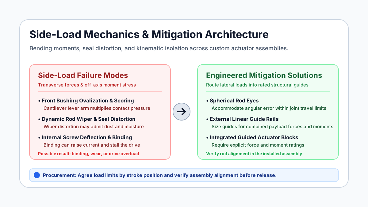
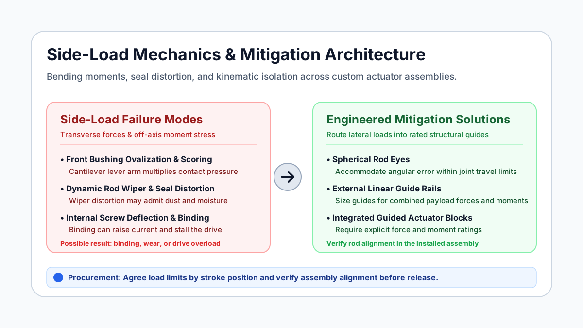
Figure 1: Conceptual failure modes and mitigation choices. This illustration is not a rated assembly drawing or evidence of product testing.
Side load, also called radial or transverse load, acts perpendicular to the actuator's stroke axis. For a transverse force applied to an exposed rod, the bending moment at the front guide is:
M = F_r × L
M: bending moment (N·m)
F_r: transverse force (N)
L: perpendicular moment arm from the front guide to the force line (m)
Measure L from the front guide, not from the rear mounting pin. The actuator's retracted pin-to-pin length plus stroke is not generally this moment arm. For example, 150 N acting 0.80 m beyond the front guide produces 120 N·m there. Whether that load is permissible depends on the rod section, support geometry, internal bearings, and supplier limits.
2. The Mechanical Anatomy of Side-Load Failure
A rod-style actuator typically contains an outer housing, drive screw, drive nut, extension tube, front guide bushing, and rod wiper. In axial loading, force travels from the rod attachment through the tube and screw/nut assembly to the thrust bearing and rear attachment. Under side load, the guides and tube must also react a bending moment.
Front Bushing Wear and Rod Scoring
A simplified two-support model illustrates why bearing reaction can exceed the external force:
Rear guide B ---- distance a ---- Front guide A ---- overhang L ---- rod tip
                                                                  ↓ F_r
Front reaction magnitude: R_A = F_r × (L + a) / a
Rear reaction magnitude:  R_B = F_r × L / a (opposite direction to R_A)
This model assumes two radial supports and a tip force, with no applied tip couple. Actual actuator construction can have a different load path. The rear guide may move with the extension tube, so a must be determined at each stroke position; do not assume it remains constant.
High reaction forces can concentrate contact at bushing edges, increase wear, and score the rod. Force alone does not establish material failure: contact area, alignment, lubrication, temperature, sliding speed, and bushing material all matter.
Rod Seal Distortion and Ingress Risk
Rod deflection can load one side of a wiper or seal more heavily than the other. Depending on the seal design and deflection, this may increase friction, accelerate wear, or permit contamination. A catalog IP rating does not approve operation with arbitrary lateral loading. The selected model's installation and test conditions govern.
Drive Screw Deflection and Nut Edge-Loading
If rod tilt transfers bending into the nut and screw, contact can become uneven and friction can rise. The resulting wear depends on the screw type, bearing arrangement, clearance, and load. Do not infer an immediate failure threshold from whether the actuator uses an Acme screw, ball screw, or planetary roller screw.
Motor Current Rise and Binding
Increased mechanical friction can raise current or trigger the drive's protection. Current is a useful diagnostic signal, but it is not a direct measurement of side force. Compare like-for-like voltage, axial load, speed, direction, and temperature; a no-load-to-loaded current increase alone cannot identify mounting damage.
3. Kinematic Root Causes of Side Loads in Real Machinery
Pivoting Arc Trajectory and Rigid Bracket Misalignment
As a hinged lid opens, its attachment point follows an arc. The actuator must be able to change orientation with that motion. For a conventional two-pin linkage, check free rotation at both ends throughout the stroke, including clearance around the housing, cable, rod eye, and brackets. A rigid flange arrangement requires a separately engineered load path; it cannot simply replace a pivot in the same mechanism.
Clevis Pin Non-Parallelism and Chassis Twist
Two rigid clevis joints can bind when their pin axes are skewed or when the frame twists in service. The LINAK LA36 mounting guidelines, under “Mounting guidelines,” call for parallel mounting pins, support at both ends of each pin, axial loading, and freedom of movement over the full stroke. This is model-specific installation guidance, not a universal numerical pin-angle tolerance.
Specify pin parallelism and bracket tolerances from the selected actuator and joint drawings. If the mechanism needs out-of-plane articulation, consider spherical joints within their rated angular travel and load limits. Check both attachments; adding one spherical joint does not automatically release every constraint.
Cantilevered Mass and Gravitational Sag
For an unsupported payload at the rod tip, its weight introduces a transverse force and a moment in a horizontal installation:
F_g = m × g
M_g = m × g × L
m: payload mass (kg); g ≈ 9.81 m/s²; L: moment arm from the front guide (m)
Support a sliding payload on rails, rollers, or another suitable bearing system. A hinged payload can instead be supported by its hinge and frame. Horizontal orientation alone does not require profile rails; the question is which component carries the weight and moments, including the rod's own weight.
4. Architectural Mitigation Strategies: Comparing the 5 Engineering Approaches
Tolomatic's actuator selection guidance recommends avoiding side loading through guides and compliance for self-alignment. The following choices apply that principle to common OEM load paths; they are not interchangeable load ratings.
Option 1: Standard Rod-Style Actuator with an Axial Load Path
Use when hinges, bearings, or a guided mechanism already carry transverse loads. Confirm the model's mounting instructions and any published radial-load limit. If no side-load rating is provided, do not assume a small percentage of axial thrust is acceptable; obtain supplier approval or remove the side load.
Option 2: Actuator with Spherical Rod Eyes
Use spherical joints to accommodate the required angular motion and mounting misalignment. Verify rated push/pull load, articulation angle with the actual spacers, pin fit, lubrication, and joint wear. They reduce constraint-induced bending but do not provide a guide for an overhung payload or increase the actuator's own radial-load rating.
Option 3: Integrated Guided Actuators
Choose a product with guide shafts or a rated carriage when compact packaging makes separate rails difficult. Request transverse-force and roll/pitch/yaw moment ratings at the actual stroke and payload offset. An anti-rotation key alone is not evidence of a load-carrying guide system. Compare the quoted assembly envelope and maintenance requirements.
Option 4: Actuator Paired with External Profile Guide Rails
Mount the payload on appropriately sized guide blocks and connect it to the actuator with a joint that transmits thrust while accommodating the necessary alignment error. Verify combined forces and moments, block spacing, rail mounting stiffness, and bearing life. Guides have finite capacities; they do not guarantee zero residual side force at the rod.
A floating alignment coupler may help release an unwanted constraint. Its permissible radial offset, angular travel, backlash, and push/pull rating must match the installation. The connection should release only the degrees of freedom the mechanism does not need constrained.
Option 5: Rodless Mechanical Linear Actuators
A rodless axis uses a traveling carriage rather than a projecting rod. Select a version with a rated load-supporting carriage; some drives require external guidance. Check the payload's center of gravity, moments, travel, sealing, lubrication, and structural mounting. Do not infer washdown capability or a maximum stroke from the architecture name alone.
5. OEM Engineering Selection & Comparison Matrix
Use this six-row matrix to request comparable quotations. Radial capacity, stroke, ingress rating, and cost are model-specific; no universal thrust percentage or cost multiplier is implied.
| Architecture | How it handles transverse loading | Evidence to request | Main limitation | Procurement comparison | Best-fit scenario |
|---|---|---|---|---|---|
| Standard rod actuator with clevis mounts | Machine hinges or bearings carry lateral loads | Mounting drawing; allowable force versus extension, if rated | Rigid pins can bind if skewed | Actuator, brackets, and alignment work | Planar hinged mechanism |
| Rod actuator with spherical rod eyes | Joints accommodate angular misalignment | Joint load and articulation limits; full-stroke clearance check | Does not support a free lateral payload | Joint hardware, spacers, wear inspection | Linkage with out-of-plane movement |
| Integrated guided rod actuator | Dedicated shafts or carriage react forces and moments | Combined-load envelope at actual offset and stroke | Guide capacity and stiffness remain finite | Complete guided assembly and service access | Compact tooling or transfer head |
| Actuator with external profile rails | Guide blocks support payload weight and moments | Per-block loads, mounting tolerance, life calculation, coupler limits | Alignment error can still load the rod | Rails, blocks, machined base, assembly labor | Offset payload on a linear slide |
| Rod actuator with extended internal guide bushing | Larger support geometry may reduce local loading | Explicit manufacturer radial-load approval and bearing limits | A larger bushing does not establish a side-load rating | Custom design, validation, replacement availability | Constrained envelope with supplier-approved loads |
| Guided rodless axis | Rated carriage carries load on the axis structure | Force/moment ratings, travel and sealing specifications | Unguided versions require separate bearings | Complete axis, supports, covers, maintenance | Long-travel transfer with a supported carriage |
RFQ handoff: Share the selected architecture and load-case drawing, including the payload center of gravity, guide spacing, full-extension position, and estimated duty cycle. This makes supplier responses easier to compare than an axial thrust figure alone.
6. How Side Load Can Compromise Ingress Protection
Separate the rated environmental test from the installed operating condition. For example, the LINAK LA36 product page lists IP66 dynamic and IP69K static. These are distinct conditions for that product; a static rating must not be presented as a moving-rod washdown approval.
Concentric rod: seal contact is distributed around the rod.
Deflected rod:  contact becomes uneven; wear or a leakage path may develop.
Design action: reduce bending and validate sealing in the installed configuration.
Heating and cooling can also change enclosure pressure. The resulting differential and leakage risk depend on temperature, enclosure volume, seal design, and any venting. No universal vacuum, seal-gap dimension, or interference fit follows from an IP code.
For outdoor or washdown equipment, request the supplier's evidence for the actual orientation, rod motion, load, temperature, cleaning chemistry, and exposure duration. Select wiper and seal materials for those conditions; PU, FKM, and NBR are not interchangeable or universally ranked. A scraper or pressure-equalizing vent may help in a suitable design, but it must be evaluated as part of the enclosure and does not compensate for excessive rod bending.
7. Screening Side Loads: A First-Principles Calculation Framework
Illustrative calculation only: The following dimensions and forces are hypothetical inputs, not measurements from a product or customer installation. Assume a quasi-static tip force, two radial supports, and no applied tip couple. Obtain actual geometry from the supplier and repeat the check at critical stroke positions. Shock, fatigue, axial buckling, screw bending, and seal behavior require separate assessment.
Step 1: Calculate the Cantilever Bending Moment
Take a transverse tip force of 150 N and a measured overhang of 0.80 m from the front guide to the force line:
F_r = 150 N; L = 0.80 m
M = F_r × L = 150 × 0.80 = 120 N·m
Do not substitute the closed pin-to-pin length for L. For the same force at L = 0.40 m, the moment would be 60 N·m. This comparison shows why extension matters without claiming either condition is allowable.
Step 2: Calculate Guide Reactions
Assume the internal support span at this extension is a = 0.12 m:
R_A = 150 × (0.80 + 0.12) / 0.12 = 1,150 N
R_B = 150 × 0.80 / 0.12 = 1,000 N
Check: R_A - R_B = 150 N (external force balance)
These are reaction magnitudes for the simplified support model, not screw thrust or an approved bearing rating. Confirm which physical components provide these supports before applying the model to an actuator.
Step 3: Screen Projected Bushing Pressure
With rod outside diameter d = 25 mm and effective bushing length b = 20 mm:
Projected area = d × b = 25 × 20 = 500 mm²
Average projected pressure P = R_A / (d × b)
P = 1,150 / 500 = 2.30 N/mm² = 2.30 MPa
This average can conceal much higher edge pressure under tilt. Compare pressure and pressure–sliding-speed product (PV) against the actual bearing material's supplier data at the specified temperature, lubrication, speed, and duty cycle. 2.30 MPa alone is neither a pass nor a fail. A material family name or a percentage of yield strength is not an adequate bearing acceptance criterion.
Step 4: Size the Guide System and Check Deflection Separately
Resolve payload weight, acceleration, process force, and moments into each guide block's load. Use the guide manufacturer's combined-load, static safety, and fatigue-life calculation, including its stated travel reference and load factors. An axial actuator thrust rating cannot establish rail capacity.
Check rod bending stress and deflection separately using the actual tube section and support arrangement. A larger rail, larger motor, or higher axial thrust rating alone does not prove the installed rod is protected. If the necessary internal geometry or permissible loads are unavailable, request a guided architecture or a supplier-reviewed assembly design before release.
8. OEM Procurement & Factory Acceptance Testing (FAT) Checklist
Attach this checklist to the RFQ and agree on measurable limits before issuing the purchase order.
- 1. Load-case drawing: Record axial force, transverse force, moments, payload center of gravity, stroke positions, acceleration, and shock conditions.
- 2. Mounting geometry: Verify pin parallelism, bracket clearances, joint articulation, and frame deflection against the selected supplier's drawings through the full stroke.
- 3. Radial-load approval: Obtain permissible force and moment limits versus extension and operating conditions, or written confirmation that the rod must be isolated from those loads.
- 4. Support and bearing limits: Confirm the actual load path, support span versus extension, bearing material limits, and calculated rod deflection.
- 5. Environmental evidence: Agree on seal materials and evidence for ingress resistance under the specified motion, orientation, cleaning, and loading conditions.
- 6. Guide and coupler selection: Verify guide-block combined loads and the connection's permitted offset, angular travel, backlash, and push/pull capacity.
- 7. FAT measurement plan: Agree on current, speed, position, temperature, and deflection measurement points, instrument accuracy, supply conditions, and stop criteria.
- 8. Endurance and release criteria: Define cycles, load spectrum, duty/rest periods, inspection intervals, wear and permanent-set limits, and the record required for acceptance.
PO Factory Acceptance Test Protocol
Distinguish prototype qualification from routine batch FAT. Endurance testing may belong in qualification; the purchase order should identify which tests apply to each production unit or sample.
- Establish comparable baselines: Record supply voltage at the actuator, axial load, speed, direction, temperature, and current versus position with a verified aligned fixture. A no-load run can identify gross binding, but loaded acceptance requires a matched axial-load baseline.
- Test the approved load envelope: Use a fixture that reproduces agreed transverse forces, offsets, mounting constraints, and critical stroke positions. Apply lateral test loads only where the supplier has approved them. For a zero-side-load installation, test the guide system's isolation of the rod instead of imposing a prohibited rod-tip force.
- Apply written acceptance limits: Compare current, speed, temperature, deflection under load, residual set after unloading, and inspection results against the drawing and supplier-approved protocol. Record the instruments, setup, sample identity, and results. Stop for binding, damage, or any agreed limit exceedance.
There is no universal 15% current-rise limit, fixed rod-deflection allowance, or cycle count that qualifies all custom linear actuators. Set each threshold from the mechanism's requirements, supplier data, and qualification evidence.
9. Frequently Asked Questions (FAQ)
Q1: What is the maximum acceptable side load for a standard linear actuator?
Use the selected model's published rating or written supplier approval at the actual extension and operating conditions. Do not derive a 2%–5% allowance from axial thrust. If the manufacturer prohibits side loading or supplies no usable radial rating, design the mechanism to carry transverse loads elsewhere and obtain confirmation before release.
Q2: How can I tell if an actuator is suffering from side-load damage?
Uneven wiper wear, opposing rod wear tracks, stroke-dependent binding, or current and noise changes can indicate misalignment or lateral loading. These symptoms can also have other causes, including contamination and damaged bearings. Secure and unload the mechanism before inspection; compare the mounting geometry and operating records with supplier guidance rather than diagnosing from current alone.
Q3: When should an OEM specify spherical rod eyes instead of standard clevis brackets?
Consider spherical joints when out-of-plane motion or frame distortion exceeds what a planar clevis arrangement can accommodate. Check angular travel at both ends, joint load ratings, spacers, pin fit, and the complete motion envelope. A spherical joint does not support an otherwise unguided payload or increase the rod's radial capacity.
Q4: Does an internal anti-rotation feature protect an actuator against side loads?
Anti-rotation prevents unwanted rod rotation; it does not by itself establish a permissible transverse force or bending moment. Some guided products provide both functions. Require explicit force and moment ratings for the complete assembly instead of assuming an anti-rotation key is a structural guide.
Q5: Can I mount a linear actuator horizontally without external guide rails?
Yes, if the manufacturer's instructions permit that orientation and the machine's hinges, rollers, bearings, or another structure carry the payload's transverse loads. Include the rod's own weight and any unsupported attachment in the review. An unapproved payload hanging from the rod tip needs a revised load path or a purpose-rated guided actuator.
Q6: What is a floating alignment coupler, and why use one with guide rails?
It transmits axial force while allowing specified relative motion to reduce unwanted mounting constraints. Available offset, angular compliance, backlash, and force ratings vary by model; not every coupler accommodates every error. Select it alongside the guides and verify that it releases the required constraint without compromising positioning or load retention.
10. Conclusion & Next Steps for OEM Sourcing
Preventing rod bending requires a defined load path, appropriate joint freedom, rated guidance, and assembly-level validation. Treat the side-load calculation as a screening aid and the supplier's model-specific limits as a prerequisite for selection.
- Benchmark supplier responses with the OEM Linear Actuator RFQ Checklist.
- Review heavy-duty actuator options and continuous-duty configurations alongside the required mounting and guidance system.
- Use the Linear Actuator Power Supply Guide when checking supply sizing and current protection.
- Contact the engineering team with linkage CAD, full-stroke geometry, load cases, and the required life and environment to discuss a custom actuator and validation plan.
11. Verifiable Sources & References
- Tolomatic — Specifying actuators 101, Part 1. Manufacturer engineering guidance, October 8, 2020. The rod-actuator selection section recommends guides and compliance for self-alignment to avoid side loading. It does not establish a universal side-load percentage.
- Thomson — Linear Actuators: Types, Benefits & Selection Guide. Manufacturer product and selection overview. Supports considering load, speed, travel, power, control, and environment together; it is not a source for the illustrative bushing-pressure calculation or an allowable radial force.
- LINAK — LA36 actuator user manual. Official manual, “Mounting guidelines”. Describes parallel mounting pins, support at both pin ends, axial loading, and freedom of movement. Apply the revision supplied with the selected configuration; no universal numerical pin-angle tolerance is inferred.
- LINAK — LA36 product specification. Manufacturer model page and document downloads. Lists IP66 dynamic and IP69K static for this model, illustrating why the operating condition must accompany an ingress rating.
Source review: October 28, 2026. Manufacturer guidance supports the stated selection and mounting principles. The worked calculation is an editorial static-equilibrium example with explicit assumptions, not manufacturer test data. Confirm current model documentation and application-specific limits before purchase or design release.
Author

Categories
More Posts
Linear Actuator Market Update (2026-W15): IP-Code and Tariff Signals OEM Teams Should Act On
Decision-first update for actuator buyers and OEM engineers based on official signals in the last 30 days, including IEC IP-code committee activity, U.S. Section 232/301 trade actions, and EU machinery trade shifts.
Linear Actuator Market Update (2026-W16): Full-Value Tariff Rules and RFQ Controls for IP/Duty/Interface Risk
Decision-level update for actuator buyers: what changed in the last 30 days, where evidence is strong vs limited, and what OEM teams should change in RFQs before the next PO cycle.
Linear Actuator Market Update (2026-W27): Proclamation 11032 Shifts Section 232 Tariff Thresholds and RFQ Sourcing Strategies
Week 27 brief for custom linear actuator buyers: Proclamation 11032 lowers the U.S.-origin metal threshold to 85%; update RFQs and HTS evidence before award.