
Linear Actuator Column Buckling and Stroke Length: An OEM Engineering Guide to Euler Limits, Compression Load Capacity, and Critical Screw Speed
Check linear actuator column buckling and stroke length limits. Compare Euler loads, screw critical speed and mounting options; prepare your OEM RFQ checklist.
Published: November 01, 2026. Content and source review: November 01, 2026. Audience: OEM mechanical engineers and industrial procurement teams worldwide; English-language guidance using SI units.
Executive conclusion: Linear actuator column buckling and stroke length must be checked together: catalog thrust alone does not establish allowable push force at full extension. For a slender column with unchanged material, section and supports, doubling the unsupported length reduces its theoretical Euler load by 75%. Doubling the travel stroke does not necessarily double that length. Check the screw and extension tube separately, then compare the compression limit with motor, nut, bearing, mounting and thermal ratings. Screw critical speed is a separate rotational limit that can apply in either push or pull operation.
Scope and engineering limits: This guide covers rod-style electromechanical actuators and ball/lead screw assemblies in custom OEM machinery. Uniform-column formulas are preliminary screening models; stepped sections, compliant joints, eccentric loading and changing guide overlap need manufacturer analysis. Worked examples are reproducible calculations with stated assumptions, not measured product ratings or customer test results. They do not establish lifting, medical or personnel-safety suitability. Final selection requires the manufacturer's load-versus-extension and speed limits for the actual installation.
Start here: If your mechanism incorporates pivoting brackets, check our companion Side-Load and Radial Force Mitigation Guide. For holding force dynamics without continuous power, review the Backdriving and Holding Brake Engineering Guide. When preparing requests for quotation, benchmark supplier claims against the OEM Linear Actuator RFQ Checklist, or submit your stroke-load profile directly to our engineering team via the Custom Engineering Contact Portal.
1. The Long-Stroke Sourcing Paradox: Catalog Force vs. Compressive Reality
Consider a hypothetical supplier listing: "Max Push/Pull Thrust: 10,000 N (2,248 lbf), Stroke: Available up to 1,000 mm, IP66 Ingress."
A buyer must establish whether the maximum force and maximum stroke are available together. The headline alone does not answer that question:
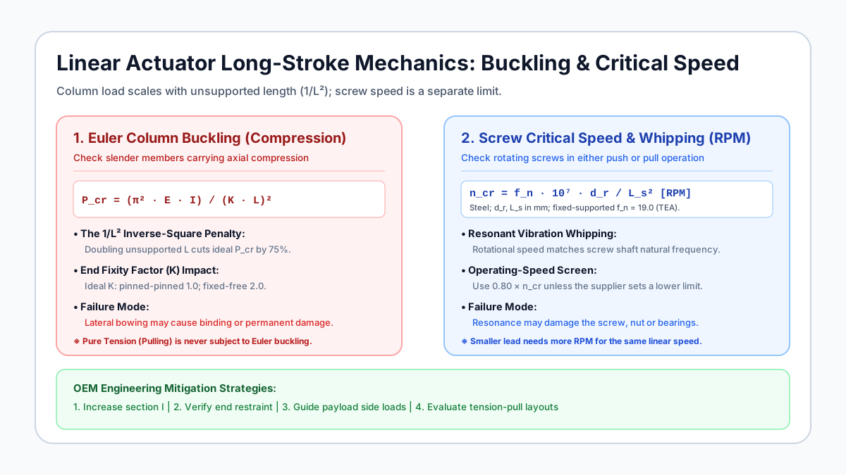
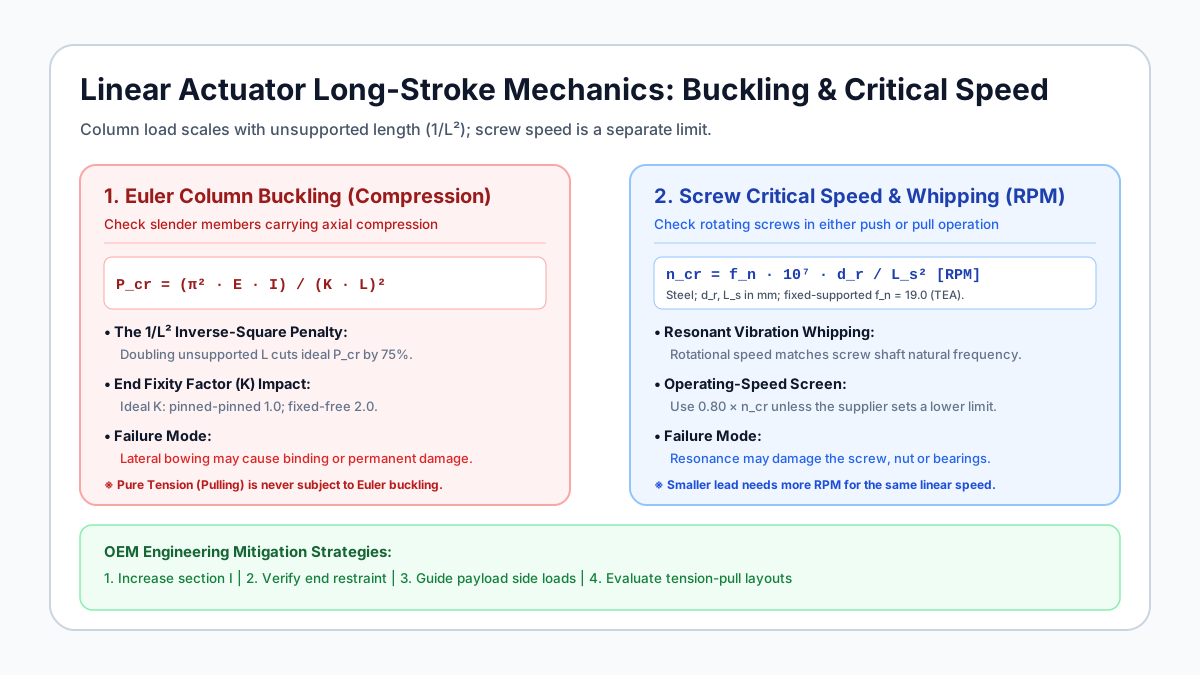 Figure 1: Architectural comparison of Euler column buckling mechanics in compression versus internal screw critical whipping speed across long-stroke actuator assemblies.
At long extension, either the screw or the extension tube may reach its column limit before the drive reaches its thrust limit. Buckling can lead to lateral deflection, binding and permanent damage; the threshold depends on geometry and supports. Tolomatic's actuator selection guidance identifies stroke, pushing force, critical speed and side-load management as separate sizing considerations.
The Two Separate Physical Failure Regimes in Long-Stroke Drives
Long-stroke electromechanical actuators are constrained by two distinct physical boundaries:
- Euler Column Buckling (Static & Dynamic Compression): An elastic lateral instability when compressive force reaches the ideal column critical load. The ideal elastic limit depends on unsupported length, section geometry, material modulus and end restraint; imperfections and eccentricity affect usable capacity.
- Critical Speed Resonance (Rotational Whipping): A dynamic resonance triggered when the internal drive screw's rotational speed (RPM) approaches its natural bending vibration frequency. Whipping causes violent radial oscillations, severe noise, premature bearing fatigue, and ball nut destruction, even under low axial loads.
2. First-Principles Mechanics: Euler's Critical Buckling Formulation
For a slender column subjected to pure concentric axial compression, the theoretical threshold where straight equilibrium becomes unstable is defined by Euler's Critical Load Formula:
P_cr = (π² × E × I) / (K × L)²

Where:
P_cr: Critical buckling load (N) — point of structural instability
E:    Young's modulus (N/mm² or MPa); approximate ambient-temperature values below
      - Carbon steel / 45# / 4140: E ≈ 206,000 to 210,000 MPa
      - 304 / 316 Stainless steel: E ≈ 193,000 to 195,000 MPa
      - 6061-T6 Aluminum alloy:    E ≈ 69,000 MPa
I:    Area moment of inertia of the cross-section (mm⁴)
L:    Unsupported column length at the assessed extension position (mm)
K:    Effective length factor governed by end fixity boundary conditions (dimensionless)
To establish a safe working compressive load (P_safe), an engineering safety factor (S_f) must be applied:
P_safe = P_cr / S_fSelect the safety factor from the applicable application requirements and manufacturer method. A factor of 2.5 can be an illustrative RFQ screening assumption, not a universal mandatory minimum. Record whether a supplier curve already includes a margin before applying another factor. Shock and personnel-safety applications require a separate risk assessment; increasing this number alone does not qualify the machine.
The Inverse-Square (1/L²) Penalty
Hold material, cross-section and K constant. If a hypothetical column has P_cr = 16,000 N at an unsupported length L = 500 mm:
P_cr(1000) = 16,000 × (500 / 1000)² = 4,000 N
P_cr(1500) = 16,000 × (500 / 1500)² ≈ 1,778 N
These are instability loads before a safety factor, not allowable product thrusts. Use each component's actual support span, not automatically actuator pin-to-pin length. For example, if a span were L = 300 mm + stroke, increasing stroke from 250 to 500 mm changes L from 550 to 800 mm; the load ratio is (550/800)² ≈ 0.473, rather than 0.25. Request the supplier's mapping from extension position to unsupported span.
Moment of Inertia (I): The d^4 Advantage
The numerator of Euler's formula is governed by the area moment of inertia (I). For cylindrical actuator rods, two geometric conditions occur:
Solid Round Rod (or Internal Screw Core):
I_solid = (π × d⁴) / 64 ≈ 0.04909 × d⁴
Where: d = solid shaft diameter or screw root diameter (mm)
Hollow Extension Tube (Standard OEM Actuator Architecture):
For an actuator with a hollow extension tube, use both outer and inner diameters:
I_hollow = π × (D⁴ - d⁴) / 64
Where:
D: Outer diameter of the extension tube (mm)
d: Inner diameter of the extension tube (mm)
For geometrically similar sections, moment of inertia scales with the fourth power of diameter (D^4). For a tube whose wall thickness changes, calculate both terms explicitly. For example, upgrading an extension tube from D = 25 mm (with 3 mm wall, d = 19 mm) to D = 35 mm (with 3.5 mm wall, d = 28 mm):
I_25 = π × (25⁴ - 19⁴) / 64 = π × (390,625 - 130,321) / 64 = 12,778 mm⁴
I_35 = π × (35⁴ - 28⁴) / 64 = π × (1,500,625 - 614,656) / 64 = 43,490 mm⁴
For the stated wall thicknesses, the second moment increases by about 240% (3.40 times). At unchanged E, L and K, the ideal Euler load has the same ratio. This does not increase the ratings of the screw, nut, motor or mounts.
3. The End Fixity Factor (K): Mounting Geometry as a Stability Multiplier
Euler's formula describes ideal column supports. Identify the restraint of the specific screw or tube in each bending plane; the external actuator mounting name alone cannot establish K. Pin clearance introduces eccentricity rather than a predictable universal adjustment to K.
| Ideal column support | K | Relative Euler load at the same L, E and I |
|---|---|---|
| Fixed-fixed | 0.50 | 4.00 times |
| Fixed-pinned, with lateral support at the pin | About 0.70 | About 2.04 times |
| Pinned-pinned | 1.00 | 1.00 baseline |
| Fixed-free | 2.00 | 0.25 times |
These ideal values are not measured stiffness values for an assembled actuator. Assess bracket, bearing and frame compliance before claiming an improvement.
1. Pinned-Pinned (Clevis-to-Clevis): K = 1.0 Idealization
- Configuration: Actuator rear housing is pinned to the chassis via a clevis bracket; the front rod eye is pinned to the driven load bracket. Both ends are free to rotate in the pivoting plane.
- Effective Length:
L_e = 1.0 × Lfor the column span being assessed. - Reality: Clevis mounting lets a pivoting mechanism change angle, but it does not provide fixed-end restraint. If pins fit loosely, slight angular play can increase effective eccentricity.
2. Fixed-Free (Cantilever Rod): K = 2.0
- Configuration: The actuator housing is rigidly flanged or foot-mounted to a rigid frame, but the extending rod tip pushes against an unguided, unsupported load (or contacts a flat surface without external guides).
- Effective Length:
L_e = 2.0 × L. - Ideal-column comparison: Because
(K × L)^2 = (2 × L)^2 = 4 L^2, the critical buckling limit drops to 25% of the pinned-pinned baseline. For an otherwise identical ideal column, a 4,000 N pinned-pinned Euler threshold would become 1,000 N under fixed-free support. Do not apply this ratio directly to a packaged actuator rating without confirming the column model.
3. Fixed-Pinned: K ≈ 0.7
- Configuration: One end of the column resists rotation and lateral motion; the other end has lateral support but can rotate. A guided carriage with an articulating rod joint may approximate the latter condition. Verify the restraints on the actual member; fixed-guided is a different boundary condition.
- Effective Length:
L_e = 0.7 × L. - Engineering Benefit: Buckling capacity increases to
1 / (0.7)^2 ≈ 2.04×the clevis baseline.
4. Fixed-Fixed: K = 0.5 (Maximum Theoretical Rigidity)
- Configuration: Both ends of the ideal column restrain rotation and lateral motion while permitting the required axial displacement. Frame and guide stiffness must support this assumption.
- Effective Length:
L_e = 0.5 × L. - Capacity Multiplier: Yields
1 / (0.5)^2 = 4.0×the buckling resistance. - Practical Warning: Pure Fixed-Fixed is rarely achievable in long-stroke machinery due to inevitable thermal expansion, frame deflection, and machining tolerances. Attempting rigid fixed-fixed without precision alignment will generate severe parasitic side loads and mechanical binding.
4. Extension Tube vs. Drive Screw: Identifying the Weakest Internal Column
In a packaged electromechanical linear actuator, the axial compression force travels through a series of structural components:
[Rear Clevis Mount]
   └──> [Thrust Bearings]
         └──> [Rotating Screw Shaft]
               └──> [Drive Nut]
                     └──> [Inner Extension Tube]
                           └──> [Front Rod Eye]
                                 └──> [External Payload]
The nose bushing supplies lateral guidance; it is not normally a serial axial thrust element. This load path is illustrative and varies by design. When evaluating buckling, determine: Which element buckles first—the internal screw or the extending piston tube?
Component A: The Internal Screw Shaft (Lead Screw or Ball Screw)
- Constraint: Confirm rear bearing restraint, any front bearing and the lateral stiffness of the nut assembly. A moving nut is not automatically an ideal lateral support.
- Unsupported Length (
L_screw): For a compression path between the thrust bearing and travelling nut, this span often increases with extension. The span used for rotational critical speed may instead be the full bearing distance; evaluate both using the actual design. - Cross-Section: Governed by the screw's minor/root diameter (
d_r), not its nominal outer thread diameter. For a20 mmball screw, the root diameter might only be16.2 mm. - Buckling Characteristic: Because the screw is enclosed inside the steel cover tube, it cannot bow indefinitely without contacting the inner wall of the extension tube. However, if the screw buckles elastically inside the tube, it creates massive frictional drag against the tube interior, accelerates nut wear, and can lock the drive.
Component B: The Outer Extension Rod / Piston Tube
- Constraint: The inner extension tube is supported at its base by the drive nut and sliding guide ring, and at the actuator nose by the front guide bushing.
- Unsupported Length (
L_rod): Measure the exposed span from the nose bushing to the rod joint, then confirm the restraint and overlap of the full tube. It is not necessarily a fixed-free cantilever when the rod tip has lateral support. - Buckling Characteristic: If the front guide bushing has significant radial clearance (backlash) or short engagement length, the extension tube behaves as a slender column subjected to external lateral deflection. Excess deflection can damage the seal or guide and cause binding.
Engineering sourcing rule: There is no universal stroke threshold separating torque-limited and buckling-limited actuators. Request the supplier's governing component, load-versus-extension curve, end-restraint assumptions and safety margin. If component dimensions are proprietary, a documented assembly-level rating for your mounting and load case is still necessary.
5. The Tension vs. Compression Asymmetry: Sourcing for Pure Pull Loads
The load direction changes the stability check for each member:
A member in pure tension does not undergo Euler column buckling. Verify the internal load path rather than assuming every component is in tension from the external pull direction.
| Selection question | Compression (pushing) | Tension (pulling) |
|---|---|---|
| Euler column instability | Check each compressed member | Does not apply to a member in pure tension |
| Material strength | Check yielding as well as instability | Check net-section strength and connections |
| Stroke dependence | Depends on changing support span and overlap | No Euler length penalty; other ratings can still vary |
| Screw rotational limit | Check critical speed and nut speed limit | Still check critical speed and nut speed limit |
| Mounts and alignment | Eccentricity reduces stability margin | Rod eyes, threads, pins and brackets still govern |
| Required supplier evidence | Allowable push curve for installed geometry | Rated pull envelope and retention/holding limits |
The Material Yield Screen in Tension
A preliminary net-section yield check is:
P_yield_screen = (A_net × σ_yield) / S_fUse the minimum tensile area and the material properties of that part. This calculation does not cover thread stripping, nut static capacity, bearing retention, fatigue, brake holding or connection failure. The lowest applicable rating governs allowable pull force.
Actionable Kinematic Redesign Strategy for OEMs
For a long-stroke high-load mechanism, compare a pull arrangement with the original push arrangement before increasing actuator size. A bell-crank or changed anchor point may remove compression from the actuator, but changes lever ratio, required force, travel and anchor reactions. Calculate the full motion envelope and verify rated pull and power-off holding capacity. Tension does not eliminate misalignment or bending from an offset load path.
6. Internal Screw Critical Speed (n_cr) and Resonant Whipping Limits
Even if an actuator passes Euler buckling calculations under static or low-speed compression, long-stroke systems face a second dynamic hurdle: screw critical speed (n_cr).
When a slender screw shaft rotates at high speed, centrifugal forces induce transverse deflections. At a specific rotational frequency—the system's fundamental natural frequency—the screw begins to vibrate violently in a resonant arc, a destructive phenomenon known as screw whipping.
Critical Speed Formulation (RPM)
For a uniform steel screw approximation, use a coefficient set consistent with the chosen diameter and units. TEA's ball screw sizing reference uses:
n_cr = f_n × 10⁷ × d_r / L_s²   [RPM]

d_r: Screw root diameter (mm)
L_s: Unsupported rotational span (mm), not the Euler effective length K × L
f_n: 4.3 fixed-free; 12.2 supported-supported;
     19.0 fixed-supported; 27.6 fixed-fixed
These coefficients exclude an operating margin. Do not mix them with coefficient sets based on nominal diameter, inches or an already-derated permissible speed. Verify bearing stiffness and any moving-nut support with the manufacturer.
The 80% Operating-Speed Screening Margin
Steinmeyer recommends approximately 80% of critical speed as a maximum operating-speed screen, with application-specific discussion for higher speeds. This is manufacturer guidance, not a universal ISO or DIN mandate:
n_operating ≤ 0.80 × n_crThe nut's permissible speed/DN value, bearings, lubrication and drive rating may impose a lower limit. Do not apply 0.80 again to a catalogue speed that already includes this margin.
Worked Example: Linear Speed, Screw Lead and Support Span
Calculated example, not a tested actuator: assume a steel screw with root diameter 16 mm, fixed-supported bearings, rotational span L_s = 950 mm and lead = 5 mm/revolution. At v = 50 mm/s:
n_operating = 60 × v / lead = 60 × 50 / 5 = 600 RPM
n_cr = 19.0 × 10⁷ × 16 / 950² ≈ 3,368 RPM
n_screen = 0.80 × 3,368 ≈ 2,695 RPM
600 RPM passes this speed screen only. It does not establish compression capacity, duty cycle or life. If the same screw instead had L_s = 2,500 mm, n_cr would be about 486 RPM and the 80% screen about 389 RPM: 600 RPM would fail.
For that longer-span example, a 10 mm/revolution lead reduces the required speed to 300 RPM. Check the resulting torque demand, resolution and backdriving/holding requirements before selecting it. Other options include a larger screw root diameter, a shorter validated support span or a supported rotating-nut architecture. External carriage rails do not automatically shorten the internal screw span.
Preparing a supplier review? Send the bearing span, lead, root diameter and required travel speed with the OEM RFQ checklist so a quoted speed can be checked against the actual assembly.
7. Engineering Mitigation Architectures: Sourcing Solutions for Long Strokes
If a candidate fails the required compression or speed envelope, compare these four design changes. A long stroke alone does not rule out a catalog actuator:
        +-------------------------------------------------------------+
        |                 LONG-STROKE MITIGATION SUITE                |
        +-------------------------------------------------------------+
               |                       |                       |
               v                       v                       v
      [Structural Upsizing]    [External Guidance]     [Kinematic Inversion]
      - Oversized Rod OD (d⁴)  - Profile Guide Rails  - Design for Tension
      - Dual Front Bushings    - Floating Rod Coupler  - Pull-to-Lift Linkage
      - Chrome-Alloy Steel     - Reduces Side Loading - Check Pull Ratings
Architecture 1: Custom Heavy-Duty Actuators with Oversized Chrome Extension Tubes
Rather than jumping to an oversized motor frame, custom linear actuator manufacturers can engineer a tailored cylinder:
- Increasing the extension tube outer diameter (
D) and wall thickness while maintaining the standard drive motor. - Selecting a suitable material and surface treatment. Higher yield strength alone barely changes elastic modulus; do not count it as an Euler stiffness increase. Austenitic 316L is not conventionally hardened by induction quenching.
- Lengthening the nose collar to house dual internal bronze or PTFE/composite guide bushings, expanding internal support spacing and reducing cantilever moment amplification.
Architecture 2: Actuators with External Profile Linear Guide Rails
Where payload side loads govern, provide separate structural guidance. A failed axial column check still requires a larger or differently supported actuator member:
- Mount the actuator parallel to appropriately sized profile linear guide rails.
- Size the carriage, rails and frame for the payload side loads and overturning moments.
- A suitable floating rod joint can reduce parasitic side load. The rod and screw still carry axial compression and can buckle; rails do not guarantee zero bow or a higher internal screw critical speed.
Architecture 3: Flange Mounting with Verified End Restraint
A stiff flange may improve housing restraint. A lower K for the compressed member is justified only when the other support, bushing overlap, joint rotation and frame stiffness produce that boundary condition. An ideal fixed-pinned column has K ≈ 0.7; bolting on a flange alone does not guarantee this value or double an assembled actuator's load capacity.
Architecture 4: Multi-Stage Telescopic Actuators
For applications with severe retracted length (pin-to-pin envelope) constraints, telescopic actuators utilize nested, stepped extension stages:
- Stage order and synchronization depend on the mechanism; do not assume the largest stage always extends first.
- Check the weakest stage and guide overlap at every extension position, using the actual linkage load profile.
- Caution: Telescopic actuators introduce complex overlapping guide overlap geometries; request documented multi-stage load-versus-extension curves from the manufacturer.
8. Sourcing & Architecture Comparison Matrix
Compare the mechanism changes below against supplier evidence. There are no universal stroke, RPM or cost ranges for these architectures; request a quote for the same load, speed, stroke, duty cycle and mounting envelope.
| Architecture | Column-stability consideration | Screw-speed consideration | Procurement trade-off / evidence to request |
|---|---|---|---|
| Clevis-mounted rod actuator | Pinned support is an initial model; check both planes | Check actual internal bearings and span | Require push-load-versus-extension curve and pin reactions |
| Larger extension tube | Higher I helps the tube; the screw may still govern | No speed gain unless screw geometry/supports change | Request screw and tube checks; compare mass and package size |
| Flange-mounted electric cylinder | Benefit depends on actual end restraint | External flange does not define screw bearing fixity | Verify frame stiffness, bushing overlap and alignment tolerance |
| Actuator with external rails | Rails manage payload moments; axial buckling remains | Rails do not automatically support the screw | Include rails, frame, coupler and alignment in the quote |
| Tension-pull linkage | Removes Euler instability only from members in tension | Rotating screw still needs a critical-speed check | Recalculate leverage, pull rating and power-off holding |
| Multi-stage telescopic actuator | Weakest stage and overlap change during travel | Depends on stage drive and internal supports | Request stage sequence and full load-versus-extension envelope |
9. Step-by-Step OEM Sizing & Calculation Workflow
Follow this systematic four-step screening workflow during the preliminary engineering phase to verify column stability before signing off on an actuator purchase order:
[Step 1: Compute Slenderness Ratio λ]
       │
       ├─► If λ ≥ λ_c  ──► Use Euler Formula (Elastic Buckling)
       └─► If λ < λ_c   ──► Review Johnson / material and local-strength limits
       │
[Step 2: Determine Peak Compression from the Motion Envelope]
       │
[Step 3: Calculate Safe Buckling Load (P_safe = P_cr / S_f)]
       │
[Step 4: Check Screw Whipping RPM (n_max ≤ 0.80 · n_cr)]
Step 1: Calculate Effective Length and Column Slenderness Ratio
Determine the column slenderness ratio (λ):
λ = (K × L) / r

Where:
r: Radius of gyration of the rod cross section = √(I / A)
   - For solid circular shaft:  r = d / 4
   - For hollow tube:           r = √(D² + d²) / 4
Calculate the critical slenderness ratio (λ_c) that separates Johnson inelastic buckling from Euler elastic buckling:
λ_c = √[ (2 × π² × E) / σ_yield ]- If
λ ≥ λ_c(Slender Column): Use Euler's classical formula (P_cr = (π^2 E I)/((K L)^2)). - If
λ < λ_c(Short/Intermediate Column): Euler alone is unsuitable. For a material and geometry where the classical Johnson approximation is applicable, a preliminary screen is:
P_cr_johnson = A × [ σ_yield - ( (σ_yield² × λ²) / (4 × π² × E) ) ]The Johnson transition is an approximation for suitable ductile materials, not a product approval rule. Confirm the material curve and check yielding, local instability and connections separately. Stroke length alone cannot identify the governing regime.
Step 2: Establish the Total Compressive Force Envelope
Account for dynamic acceleration spikes, friction, and environmental forces:
F_total_comp = (F_process + F_gravity + F_inertia + F_friction + F_wind) × K_shock

Where:
F_inertia = m × a  (Mass × peak acceleration during motion start/stop)
K_shock: Application-specific factor, justified by measured loads or the design standard
Resolve signed forces through the linkage at each position; do not count gravity twice if it is already part of a stated static load. Select the maximum compression case and document how shock allowance and safety factor are applied.
Step 3: Verify the Column Safety Margin
Verify that:
P_safe = (P_cr / S_f) ≥ F_total_compIf P_safe < F_total_comp, redesign the assembly:
- Increase extension tube diameter
D. - Improve verified end restraint or shorten the unsupported span.
- Switch mechanism kinematics to tension pull.
Step 4: Verify Screw Critical Speed Margin
Calculate maximum operational screw RPM based on linear travel speed:
n_operating = (60 × v_max) / lead   [RPM, v_max in mm/s; lead in mm/rev]
n_safe_limit = 0.80 × n_cr
Confirm that n_operating ≤ n_safe_limit. If the screw operates above this ceiling, consider a larger lead, larger screw root diameter or shorter supported span, then recheck torque and holding requirements. Lead is axial travel per revolution; for a multi-start screw, lead equals pitch times the number of starts.
10. OEM Procurement & Factory Acceptance Testing (FAT) Checklist
Attach these requirements to the RFQ so engineering and purchasing can agree the operating envelope and acceptance evidence before ordering.
Part A: Technical RFQ Specifications Checklist
- 1. Compression vs. Tension Force Profile: Explicitly specify maximum peak force in compression (
F_push) and tension (F_pull) separately, along with exact stroke positions where peak loads occur. - 2. Full Pin-to-Pin Envelope & Extension Length: Provide 3D linkage drawings defining retracted length (
L_retract), full extended length (L_extend), and mounting pin centerlines. - 3. End Fixity & Mount Identification: Show the actual mounts, joint freedoms and clearances in both planes. Request the supplier's column model and justified K; a flange or trunnion name alone does not determine it.
- 4. Extension Tube Dimensions & Metallurgy: Require supplier drawings to declare tube outer diameter (
D), wall thickness (t), material grade (e.g., 20MnV6, 45# chrome-plated steel, 316L), and yield strength (σ_y). - 5. Internal Screw Specifications: Mandate disclosure of screw root diameter (
d_r), pitch/lead, screw material, and calculated critical whipping speed (n_cr). - 6. Documented Compression Envelope: Request an allowable push-load-versus-extension curve for the assembled actuator and actual mounting. Record the governing component, calculation/test basis, safety factor and whether margins are already included.
- 7. Dynamic Guide Bushing Design: Confirm the nose guide bushing material (bronze, PTFE composite, POM) and bearing engagement length at full extension.
- 8. Maximum Velocity & Acceleration Envelope: Define peak linear velocity (
mm/s) and acceleration profile (m/s^2) to check manufacturer-permitted speed at every relevant span; distinguish an undiminished critical speed from an already-derated catalog speed.
Part B: Factory Acceptance Testing (FAT) Quality Protocol
Agree a guarded test plan with the actuator manufacturer before testing pilot units. The following is an acceptance-plan checklist, not a universal overload procedure or an existing test report. Define specimen count, load cases, dwell, instrumentation and stop criteria in the purchase specification.
- Static compression verification: Match the installed supports and the worst combination of load and extension, which need not occur at full stroke. Record lateral deflection under load and residual set after unloading. Proof-load magnitude, dwell and residual-set tolerance require manufacturer approval and application-specific limits; do not assume a 150% overload is acceptable.
- Loaded full-stroke travel: Use the agreed speed, load profile and rated duty cycle. Record force, position, current and temperature against a baseline. Set cycle count and acceptance limits in advance. A current rise can indicate friction or binding but cannot by itself diagnose buckling or establish fatigue life.
- Speed and vibration verification: Remain inside the manufacturer-approved operating envelope with suitable guarding. Compare vibration and noise with a documented baseline. Do not deliberately cross resonance; unloaded smooth running does not prove compression capacity.
- Inspection and release evidence: Check guides, seals, connections and backlash after testing; agree any sample teardown with the manufacturer. Release only when the required measurements and supplier envelope meet the stated acceptance limits. Pilot acceptance is not a substitute for application-life qualification.
11. Frequently Asked Questions (FAQ)
Q1: Why can compressive push capacity decrease with extension while pull capacity behaves differently?
A compressed slender member can lose lateral stability as its support span grows; the ideal Euler limit scales with 1/L² when the other terms stay constant. A member in pure tension does not suffer Euler buckling. Pull capacity is still limited by the screw/nut, rod, connections, bearings, drive and duty cycle. Do not assume 100% catalog pull capacity at every extension without the supplier's envelope.
Q2: Can I prevent column buckling by adding an anti-rotation rod or external guides?
Anti-rotation alone does not establish lateral column support. External rails can carry payload side loads, but the actuator's compressed rod and internal screw still need stability checks. Only a support with documented stiffness and load transfer can justify a changed span or end condition.
Q3: What is the difference between Johnson buckling and Euler buckling?
Euler models slender elastic columns. Johnson is an approximate transition model for suitable intermediate columns where material nonlinearity matters. Choose a method from effective slenderness, material properties and the validated component model; there is no universal 300 mm or 500 mm stroke boundary. Very short members also need direct yield and local-strength checks.
Q4: How do I distinguish column buckling from side-load damage?
Buckling may appear under high compression at a long unsupported span; side load may produce one-sided guide or seal wear throughout travel. These signs overlap, and elastic buckling need not leave a permanent bow. Preserve load/position records and inspect mounts, guides and the screw before assigning a cause. See the side-load mitigation guide for alignment checks.
Q5: Does screw lead change critical speed?
Lead changes the RPM needed for a linear speed: n = 60v/lead. At unchanged shaft geometry and supports, it does not directly change the shaft's bending critical speed. Larger lead reduces required RPM but changes drive torque, resolution and holding behavior. On a multi-start screw, use lead rather than thread pitch in the speed calculation.
Q6: Can spherical rod eyes prevent column buckling?
Spherical joints can reduce bending caused by angular misalignment within their travel limits. They allow rotation, so a column with lateral support at both articulated ends may be screened as pinned-pinned (K = 1). They do not create fixed-end restraint or eliminate buckling under axial compression. Check actual joint freedom, eccentricity and both bending planes.
12. Conclusion & Next Steps for OEM Sourcing
Long-stroke linear actuator engineering requires rigorous management of structural stability. A headline thrust rating leaves the full-extension compression limit and screw speed envelope unresolved.
Use the calculations to reject unsupported proposals, compare push and pull arrangements, and request a documented operating envelope. Agree safety margins and acceptance limits with the supplier before purchase; a screening calculation cannot guarantee field reliability.
Next Steps for Your Project:
- Audit your RFQ parameters: Use our OEM Linear Actuator RFQ Checklist to benchmark supplier data sheets.
- Review Heavy-Duty Actuator Platforms: Explore structural options across our 12V Heavy-Duty Actuator Series and Continuous-Duty Industrial Cylinders.
- Evaluate Power and Drive Sizing: Consult the Linear Actuator Power Supply Guide to balance motor current draw under full stroke.
- Request a Custom Feasibility Review: Contact our engineering team with your stroke length, compressive load profile, mounting geometry, and CAD envelope for a dedicated Euler buckling and critical speed audit.
13. Verifiable Sources & References
- TEA — Ball Screw Sizing. Provides a steel-screw Euler screen, root-diameter critical-speed coefficients and an explicit 0.8 operating margin. Its scope excludes life and several assembly effects. Formula definitions and limits.
- August Steinmeyer — Critical Speed. Explains bearing restraint, moving-nut support and its approximately 80% operating recommendation. Its nominal-diameter coefficients must not be interchanged with a root-diameter formula. Critical-speed guidance.
- Tolomatic — Specifying actuators 101, Part 1. Discusses stroke/pushing-force constraints, critical speed, duty cycle and guidance against side loading. This is actuator-selection guidance, not a certification standard or a universal buckling coefficient table. Actuator sizing considerations.
Source review date: November 01, 2026. The links above support the specified sizing principles, not product performance claims, universal FAT limits or safety certification. Numerical examples are calculated from the stated inputs; use current model-specific manufacturer documentation for purchasing decisions. Recheck this guide within 12 months, or earlier if a cited method or product configuration changes.
Author

Categories
I): The d^4 AdvantageSolid Round Rod (or Internal Screw Core):Hollow Extension Tube (Standard OEM Actuator Architecture):3. The End Fixity Factor (K): Mounting Geometry as a Stability Multiplier1. Pinned-Pinned (Clevis-to-Clevis): K = 1.0 Idealization2. Fixed-Free (Cantilever Rod): K = 2.03. Fixed-Pinned: K ≈ 0.74. Fixed-Fixed: K = 0.5 (Maximum Theoretical Rigidity)4. Extension Tube vs. Drive Screw: Identifying the Weakest Internal ColumnComponent A: The Internal Screw Shaft (Lead Screw or Ball Screw)Component B: The Outer Extension Rod / Piston Tube5. The Tension vs. Compression Asymmetry: Sourcing for Pure Pull LoadsThe Material Yield Screen in TensionActionable Kinematic Redesign Strategy for OEMs6. Internal Screw Critical Speed (n_cr) and Resonant Whipping LimitsCritical Speed Formulation (RPM)The 80% Operating-Speed Screening MarginWorked Example: Linear Speed, Screw Lead and Support Span7. Engineering Mitigation Architectures: Sourcing Solutions for Long StrokesArchitecture 1: Custom Heavy-Duty Actuators with Oversized Chrome Extension TubesArchitecture 2: Actuators with External Profile Linear Guide RailsArchitecture 3: Flange Mounting with Verified End RestraintArchitecture 4: Multi-Stage Telescopic Actuators8. Sourcing & Architecture Comparison Matrix9. Step-by-Step OEM Sizing & Calculation WorkflowStep 1: Calculate Effective Length and Column Slenderness RatioStep 2: Establish the Total Compressive Force EnvelopeStep 3: Verify the Column Safety MarginStep 4: Verify Screw Critical Speed Margin10. OEM Procurement & Factory Acceptance Testing (FAT) ChecklistPart A: Technical RFQ Specifications ChecklistPart B: Factory Acceptance Testing (FAT) Quality Protocol11. Frequently Asked Questions (FAQ)Q1: Why can compressive push capacity decrease with extension while pull capacity behaves differently?Q2: Can I prevent column buckling by adding an anti-rotation rod or external guides?Q3: What is the difference between Johnson buckling and Euler buckling?Q4: How do I distinguish column buckling from side-load damage?Q5: Does screw lead change critical speed?Q6: Can spherical rod eyes prevent column buckling?12. Conclusion & Next Steps for OEM SourcingNext Steps for Your Project:13. Verifiable Sources & ReferencesMore Posts
Linear Actuator Market Update (2026-W19): HTSUS Technical Corrections and RFQ Controls for Section 232 Exposure
Week 19 brief for custom linear actuator buyers: HTSUS technical corrections, Section 232 RFQ controls, and immediate OEM actions before PO release decisions.

Linear Actuator Spec Inflation: A Procurement Guide to Verifying Force, Duty Cycle, and Lifespan Ratings
Verify linear actuator force, duty cycle, and L10 life claims before RFQ award. Use supplier evidence checks to avoid inflated specs and early failures.

Replacing Hydraulic Cylinders with Heavy-Duty Electric Actuators: The 2026 OEM Guide to TCO and ESG
Compare hydraulic cylinders with custom electric linear actuators for 2026 OEM TCO, ESG, sizing trade-offs, and RFQ inputs before a conversion project.